

1/13/2025
I spent some real time today trying to figure out how the heater in this car works, and before we launch, I want to tell you –
- It’s not what you think
- I’m still not sure I get it, and I’m not sure anyone but the engineer does either
Let’s start with a favorite drawing of mine…
Obviously related, but probably won’t help you understand the issue – but damn it, it’s cute, right?
Alternating Current (AC)
Emma does not use Alternating Current (AC) power. She uses Direct Current (DC), coming from the battery, which is a 12 volt cell.
Your house uses AC power – 120 volts for the regular plugs and 240 volts for the big things like a clothes dryer.
It’s called alternating current (we’re going to distill this down – it’s much more complex than I’m making it) because it literally changes direction over and over.
Over and over – 60 times per second, as a matter of fact. That equates to 60Hz.

Since the power goes back and forth over and over, a ground in AC power is an off-ramp for faults (literally it eventually directs it to the earth).
I need you to remove that concept of ground from your brain for the remainder of this blog post.
Direct Current (DC)
I want you to think of direct current (for this context) as… well, this:
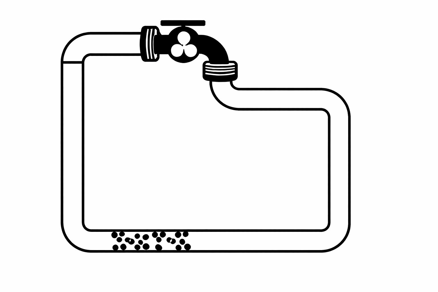
The faucet is the battery, the muck in the pipe is some resistance.
That’s how power in Emma works, with the caveat that a lot of the return pipe is actually the chasis of the car. We’ll get to that.
Emma and the Not-So-Great Heater
Right, so up front I’m going to drop this diagram I made, and we’ll discuss.
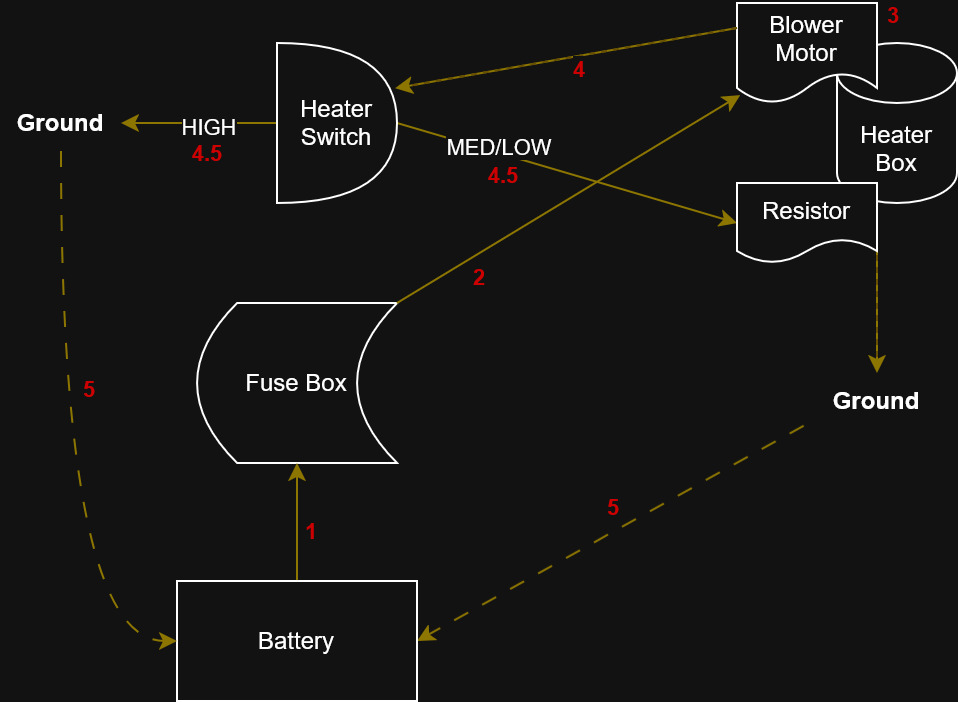
Don’t get overhwelmed, the steps are numbered and we’ll walk through that.
- BATTERY to FUSE box – I think everyone know this is how it works. It’s how it works in your house, too – just on a much larger scale
- FUSE box to BLOWER motor. What I need you to plant in your brain for this is that the FUSE box provides a 12v supply to the BLOWER motor.
- Barring all else, BLOWER motor will do BLOWER motor things, meaning it’ll go full blast – like if we remove the rest of this chart, that’s what would happen
- Current flows through the BLOWER motor and exits via a return lead to the SWITCH
- 4.5a & 5a – If the SWITCH is on HIGH – the SWITCH just lets the current go to GROUND, creating a loop that powers the BLOWER motor at full blast
- 4.5b & 5b – If the SWITCH is on MEDIUM or LOW, the SWITCH sends that live load to the RESISTOR, which expends a portion of that energy into the HEATER BOX as heat. The RESISTOR is grounded, and the completed circuit now allows reduced current
- This in turn reduces the speed of the blower motor!
- This step is technically articulated in the previous bullets, but what wasn’t said here was that when you look at the drawing above, 5 is technically Emma’s chasis.
- WHY? – In this model, the whole point of GROUND is to find a path back to the battery. That’s it. It completes the circuit. The negative terminal of the battery (also a ground) terminates to the chasis of the car, right? Well, that becomes a power return path to the battery – like the pipe illustration above
All that to say – we’re missing the SWITCH > GROUND connection on Emma right now, which is why no matter what we set the SWITCH to, the BLOWER motor runs at 100%.
If you made it this far, thank you for being a loyal reader, and know that this blog post was more for future-Brian than anything else.
Leave a Reply